-

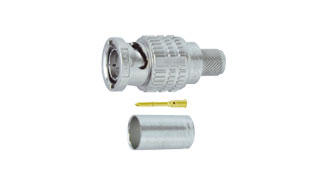
HBCP-LD25HD
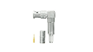
75 ohm Micro BNC Crimp Plugs [ Right Angle ]
Canare's right-angle plug is suitable for Micro BNC installations with limited depth.
- TECH DATA
- TECH NOTE
- DOWNLOAD
HBCP-L Series [ Right Angle ]
| Model | Suitable Cable | Center Pin | Sleeve | Boot | Die Set | Standard package | |
|---|---|---|---|---|---|---|---|
| Canare | Others | ||||||
| HBCP-LD25HD | L-2.5CHD, L-2.5CHLT | 1855A | BN1227 | BN7136 | - | TCD-D253F | 20pcs |
| HBCP-LD25HW | L-2.5CHWS | - | BN1227 | BN7141 | - | TCD-D253F | 20pcs |
| HBCP-LD33UHD | L-3.3CUHD | - | BN1229 | BN7003A | - | TCD-D253F | 20pcs |
| HBCP-LD53 | L-4.5CHD, V4-4.5CHD | 1694A | BN1230 | BN7016 | - | TCD-D534F | 20pcs |
Key Features and Benefits
- Return Loss: 24dB @ 3GHz, 20dB @ 6GHz, 13dB @ 12GHz
- Canare crimp design ensures quick and reliable
- Gold plated “snap locks” center pin and beryllium copper outer contact.
- Gold plating on the contact pin prevents deterioration, even after years of use.
- Lock mechanism used on insulation improves reliability by preventing shifting or detaching of the center pin.
- Note:
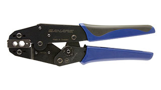
- Be sure to use Canare Crimp Tool.
- Note:
- For crimping instructions, please refer to this page or the instruction manual.
Technical Note
Voltage Standing - wave Ratio (VSWR) and Return Loss
Terminating the receiving end of a limited length coaxial cable using a resistance value not equal to its characteristic impedance creates a reflected wave that returns back down the cable to the sending end. The result is interference developing between the travelling wave and the return wave which results in a standing wave that causes voltage levels to fluctuate. The degree to which terminating resistance matches the characteristic impedance is indicated using the VSWR or voltage standing-wave ratio standard shown in Fig. 1. Going hand in hand with the VSWR ratio is the return loss factor which measures the size of the reflected wave current in relation to the travelling wave current. (See Fig. 2)
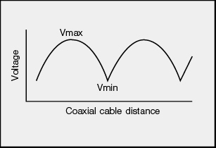
Fig. 1 Voltage Distribution Over Coaxial Cable
| VSWR | Return Loss (dB) |
|---|---|
| 2 | 9.54 |
| 1.5 | 13.98 |
| 1.2 | 20.83 |
| 1.1 | 26.44 |
| 1.05 | 32.26 |
| 1.02 | 40.09 |
| 1.01 | 46.06 |
Fig. 2 VSWR to Return Loss Conversion Table