-
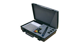
Hand Crimp Tools + Die Sets -
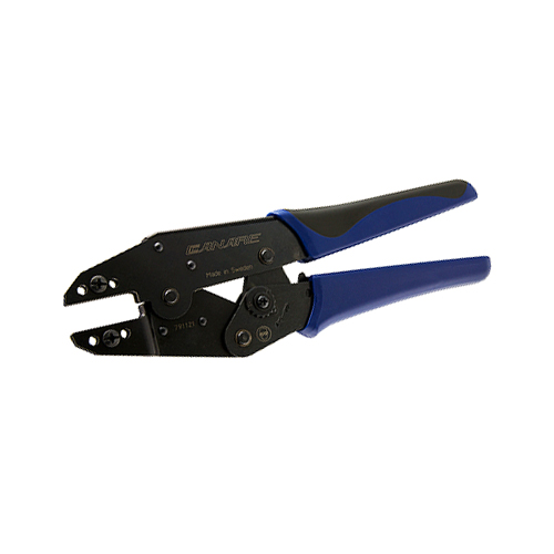
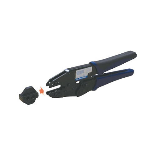
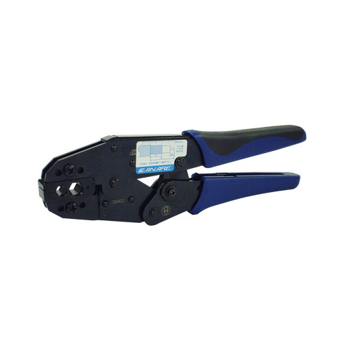
Hand Crimp Tools (TS-1) -
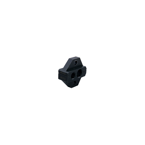
Die Sets (TCD-451CA) -
Hand Crimp Tools + Die Sets -
Die Sets
Crimp Tools
Canare crimp tool offers reliable high-quality crimping performance in an easy-to-use design.
- TECH DATA
- TECH NOTE
- DOWNLOAD
Crimp Tools
| Model | Description | Standard package |
|---|---|---|
| TC-1 | Canare standard hand crimp tool. | 1 |
| TC-2 | TCD-8HD, TCD-96C |
Key Features and Benefits
- Select the appropriate Die Set to suit the individual connector
- Hand crimp tool is required for Die Set, and sold separately
- Die Set are interchangeable
Die Sets
| Model | Pin crimp #1 (mm) | Pin crimp #2 (mm) | Sleeve crimp #1 (mm) | Sleeve crimp #2 (mm) | Hand Crimp Tools | Standard package |
|---|---|---|---|---|---|---|
| TCD-1DB | - | - | 3.94 | - | TC-1 | 1 pc |
| TCD-31C | 1.37 | - | 6.75 | - | ||
| TCD-3151D | 1.92 | - | 8.36 | 6.75 | ||
| TCD-316C | 1.35 | - | 9.4 | 6.75 | ||
| TCD-35CA | 1.35 | - | 7.6 | 5.85 | ||
| TCD-35D | 1.92 | - | 7.6 | 5.85 | ||
| TCD-35DF | 1.92 | 2.1 | 8.05 | 5.82 | ||
| TCD-4CA | 1.35 | - | 6.48 | - | ||
| TCD-451CA | 1.35 | - | 8.36 | 6.4 | ||
| TCD-5CF | 1.31 | - | 8.05 | - | ||
| TCD-5HD | 1.87 | - | 8.05 | - | ||
| TCD-55FA | 1.35 | 2.1 | 8.05 | - | ||
| TCD-55UHD | 1.62 | - | 8.05 | - | ||
| TCD-57C | 1.62 | - | 8.5 | - | ||
| TCD-65C | 1.92 | - | 9.4 | 7.6 | ||
| TCD-67HD | 2.1 | - | 10.2 | - | ||
| TCD-7CA | 1.87 | - | 10.2 | - | ||
| TCD-8HD | 2.4 | - | 11.26 | - | TC-2 | |
| TCD-96C | 1.92 | - | 11.26 | 9.4 | ||
| TCD-D253F | 1.1 | - | 5.1 | 5.85 | TC-1 | |
| TCD-D534F | 1.27 | - | 7.55 | 6.4 |
Compatible connector
| Compatible connector | |
|---|---|
| TCD-35CA | BCP-D33UHD, BCP-B25HD, BCP-B25HW, BCP-B3F, BCP-B45HW, BCP-B53, CP-A25, BCP-A25F, BCP-A3, BCP-A3AHD, CP-A3F, BCP-A33, BCP-A5, BCP-A5F, CP-VA3, BCP-VA5, CP-LC3, BCP-LC3F, BCP-LC5, MBCP-C25F, MBCP-C3F, MCF-V5C3, MCM-V5C3, RCAP-C25HD, RCAP-C3A, RCAP-C3F, RCAP-C53, RCAP-C5A, FP-C25HD, FP-C3, FP-C3F, FP-C53A, FP-C5, SPP-C33-CL |
| TCD-35D | BP-C3, BP-C4, BP-C5, TNP-C3, TNP-C4, TNP-C5, RCAP-C3GS |
| TCD-35DF | BP-C5FA, BP-C51F, TNP-C5F, NP-C5F, NP-C51F, SP-C5F, SJ-C5F, SMAP-C3F, SMAP-C5F, SMAJ-C3F, SMAJ-C5F |
| TCD-4CA | BCP-B31F, BCP-B4F, BCP-A4, BCP-A4F, MBCP-C4, MBCP-C4F, BCJ-C4, RCAP-C4A, RCAP-C4F, FP-C4, FP-C4F, VP-C4A, VWP-C4A, MVP-C4 |
| TCD-451CA | BCP-B31F, BCP-B4F, BCP-A4, BCP-A4F, CP-A52, MBCP-C4, MBCP-C4F, BCJ-C4, RCAP-C4A, RCAP-C4F, FP-C4, FP-C4F, FP-C52, VP-C4A, VWP-C4A, MVP-C4 |
| TCD-5CF | BCP-B5F, BCP-B51F, BCP-LC5F, MBCP-C5F, RCAP-C5F, FP-C5F |
| TCD-5HD | BCP-C5HD |
| TCD-55FA | BCP-B5F, BCP-B51F, BCP-LC5F, MBCP-C5F, RCAP-C5F, FP-C5F, BP-C5FA, BP-C51F, TNP-C5F, NP-C5F, NP-C51F, SP-C5F, SJ-C5F, SMAP-C5F, SMAJ-C5F |
| TCD-55UHD | BCP-D55UHD, HBCP-D55UHD |
| TCD-57C | BCP-D55UHW, BCP-D57 |
| TCD-67HD | BCP-C6HD, BCP-C7HD |
| TCD-7CA | BCP-C7A, BCP-C7FA, FP-C7FA |
| TCD-D253F | DCP-C25HD, DCP-C25HW, DCP-C3F, MDM-V4C25HW, MDF-V4C25HW, VP-C25HW, VWP-C25HW, MVP-C25HW, MCVP-C25HW,
BCJ-D25HD, BCJ-D25HW, BCJ-D33UHD, HBCP-D25HDA, HBCP-D25HWA, HBCP-D33UHDA |
| TCD-D534F | DCP-C4F, DCP-C53, DCP-C53A |
| TCD-8HD | BCP-D8UHD |
| TCD-8DF | SP-C8F |
Crimp Connector Assembly Instructions
Confirm compatibility of the connector and cable prior to assembly.
1 Slide the crimp sleeve over the cable and strip the jacket, braided shield, and insulation of the coaxial cable as shown at left.
- For cables with stranded inner conductor, twist the strands in the same direction as plied after removing the insulation.
- For a crimp sleeve with steps, slip it over the cable from the stepped end, as in the diagram.
- If any metal foil shield is left on the cable, it may get stuck in the mouth of connector, making insertion impossible.
- Remove all stray strands and offcuts of the metal foil shield to avoid possible short circuiting.
- Make sure the inner conductor is free of all insulation debris and offcuts to ensure complete crimping.


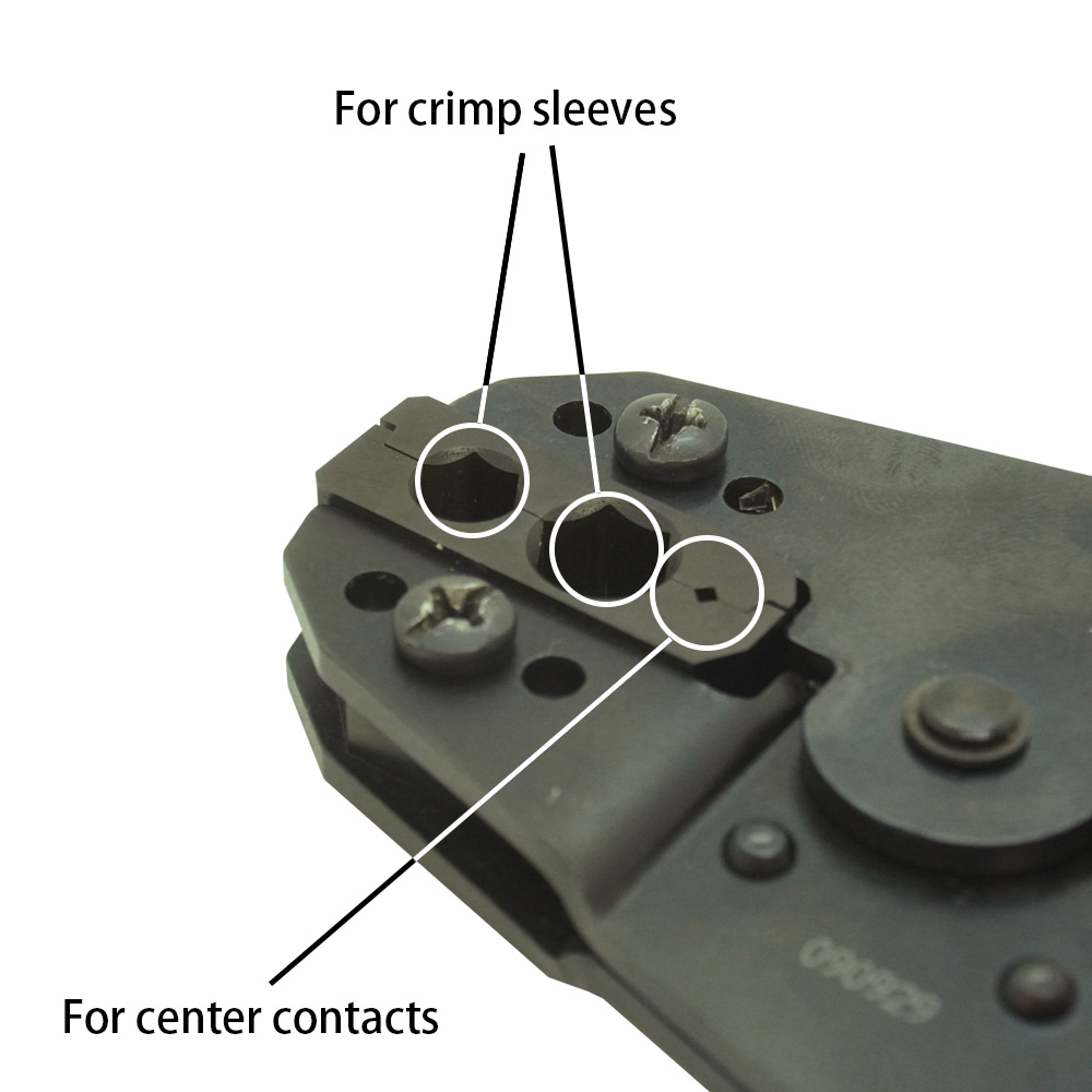
2 Place the center contact pin of the connector on the inner conductor of the cable and crimp the center contact pin at the correct position (without remaining a gap) as shown at left, using the specified crimp tool and Die Set.
- To confirm the crimping properly, measure the crimp height after removing burrs with a knife. If it is not within the ideal value range, adjust the crimp tool.
- Do not crimp the center contact pin at the stepped root end.
- Confirm the center contact pin is crimped straight to the inner conductor. If the center contact pin is slanted, align it gently.

3 Hold the cable and push it into the connector body until the center contact pin is locked in place. You may feel a click sound when the contact pin is locked.
- Pull the cable gently (less than 4.5 lbs or 19.6 N) to confirm that is locked.

4 Slide crimp sleeve up against connector body over the braided shield until it butts against the connector body. Center the die over the crimp sleeve and crimp in place, using the specified crimp tool and Die Set.
- Do not pull the cable while crimping is executed.

Adjusting Crimp Tool
1. Measuring Crimping height
Crimp height is measured after the crimp is made. As shown in the figure, the sum of the measured values for both directions is divided by two to arrive at the crimp height. The ideal value range for the BCP-A3 connector, for example, is 1.4 mm to 1.5 mm. When this value is lower (overcrimping occurs) than the recommended crimp height, the crimp becomes very hard. A value higher (undercrimping occurs) than the recommended value can result in increased electrical resistance and a physically weaker crimp. Either digital calipers or a micrometer should be used for measuring crimp height.
2. Measuring Frequency
Crimp height is measured prior to commencing use of the crimp tool and always when changing the crimping die. After this, the crimp height is regularly measured after about each 1,000 crimps.

Refer to the separately included manual for the appropriate crimp height values for individual connectors.
3. Tool Measuring Procedures
Crimp force increases and crimp height decreases when the tool’s adjuster dial is turned in the direction of the 9. The dial is adjusted by first releasing it using a screwdriver.

F A Q
- Does it matter in which direction crimp sleeves are attached ?
-
For BCP-A3-use and other non-stepped (straight type) crimp sleeves, it does not matter in which direction the crimp sleeve is attached. The attachment direction also does not matter for BCP-A5F-use and other specific-use types that have a chamfer (groove) at one end of the crimp sleeve. However, stepped crimp sleeves such as those for BCP-C1, etc. are directional and must be attached in the direction shown in the diagram below, with the cable threaded through the sleeve starting from the end with the step (that is, the end with smaller-diameter hole).

- What should be done with a metal foil shield?
- Strip the metal foil shield to the root of the braided shield (to the edge of the jacket). If any metal foil shield is left on the cable, it may get stuck in the mouth of connector, making insertion impossible.
- Why do some BNC plugs made by other companies have a sharp point at the tip of the central contact? Are these compatible with Canare’s BNC receptacles?
-
The central contact is pointed in conformance with the JIS standard for 50Ω BNC connectors. The central contacts on Canare’s connectors conform to the MIL standard, and therefore are not pointed. These two different shapes simply offer different ways to guide the plug into the female receptacle and have no direct effect on contact quality.
The actual contact surfaces on Canare’s BNC connectors are designed in conformance with JIS standards and therefore pose no compatibility problems.
- Is it possible to use cables not listed in the connector compatibility table as long as they are close to the dimensions of those listed?
- No. While connection may be possible, performance may be adversely affected. Even if the connection appears to work, factors such as electrical instability, weak cable contact strength and others may cause problems during actual use. Therefore, it is necessary to test and evaluate whether it is actually possible to use the configuration in question. Particular caution should be used when crimping is involved.
- What is meant by “cable contact strength”?
- Cable contact strength refers to the maximum load borne by the cable when exerting tensile force to remove it from the connector. For Canare products, “cable contact strength” refers to the contact strength of a cable’s outer conductor, not including the pull - out strength of the central contact or the contact strength of the inner conductor.
- What is the approximate insertion loss associated with connectors?
- The value varies depending on the connector, but for BNC plugs, the value is approximately 0.1 dB per plug (DC-2 GHz).