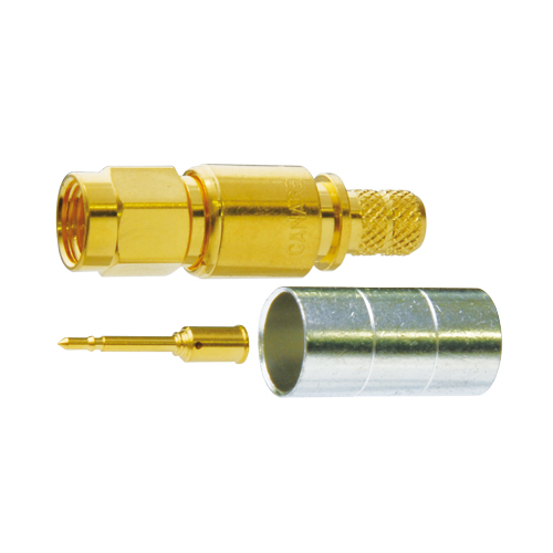
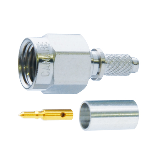
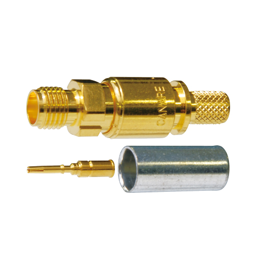
50 ohm SMA Crimp Plugs
SMA Crimp Plugs for telecommunications equipment and measuring instruments.
Key Features and Benefits
- VSWR of 1.1 or less up to 2 GHz, 1.2 or less up to 4 GHz. (SMAP-C1: VSWR of 1.2 or less up to 2 GHz)
- Canare crimp design ensures quick and reliable installation (SMAP-C1 has solder center contact)
- Note:
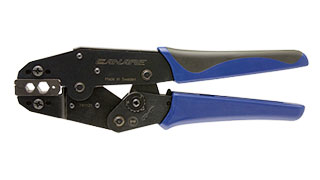
- Be sure to use Canare Crimp Tool.
- Tech Data
- Tech Note
- Downloads
StraightCrimp Type
| Model | Suitable Cable | Die Set | Standard package |
|---|---|---|---|
| SMAP-C1 | 1.5D-QEW | TCD-1DB | 20 pcs |
| SMAP-C31A | L-3D2W, 3D-2W | TCD-3151D | |
| SMAP-C3F | L-3DFB | TCD-35DF | |
| SMAP-C51 | L-5D2W, 5D-2W | TCD-3151D | |
| SMAP-C5F | L-5DFB, 5D-FB | TCD-35DF, TCD-55FA |
Straight JackCrimp Type
| Model | Suitable Cable | Die Set | Standard package |
|---|---|---|---|
| SMAJ-C3F | L-3DFB | TCD-35DF | 20 pcs |
| SMAJ-C51 | L-5D2W, 5D-2W | TCD-3151D | |
| SMAJ-C5F | L-5DFB, 5D-FB | TCD-35DF, TCD-55FA |
Technical Note
Voltage Standing - wave Ratio (VSWR) and Return Loss
Terminating the receiving end of a limited length coaxial cable using a resistance value not equal to its characteristic impedance creates a reflected wave that returns back down the cable to the sending end. The result is interference developing between the travelling wave and the return wave which results in a standing wave that causes voltage levels to fluctuate. The degree to which terminating resistance matches the characteristic impedance is indicated using the VSWR or voltage standing-wave ratio standard shown in Fig. 1. Going hand in hand with the VSWR ratio is the return loss factor which measures the size of the reflected wave current in relation to the travelling wave current. (See Fig. 2)
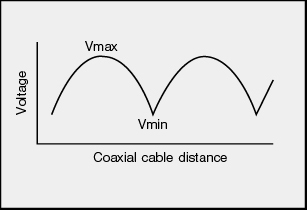
Fig. 1 Voltage Distribution Over Coaxial Cable
| VSWR | Return Loss (dB) |
|---|---|
| 2 | 9.54 |
| 1.5 | 13.98 |
| 1.2 | 20.83 |
| 1.1 | 26.44 |
| 1.05 | 32.26 |
| 1.02 | 40.09 |
| 1.01 | 46.06 |
Fig. 2 VSWR to Return Loss Conversion Table
