-
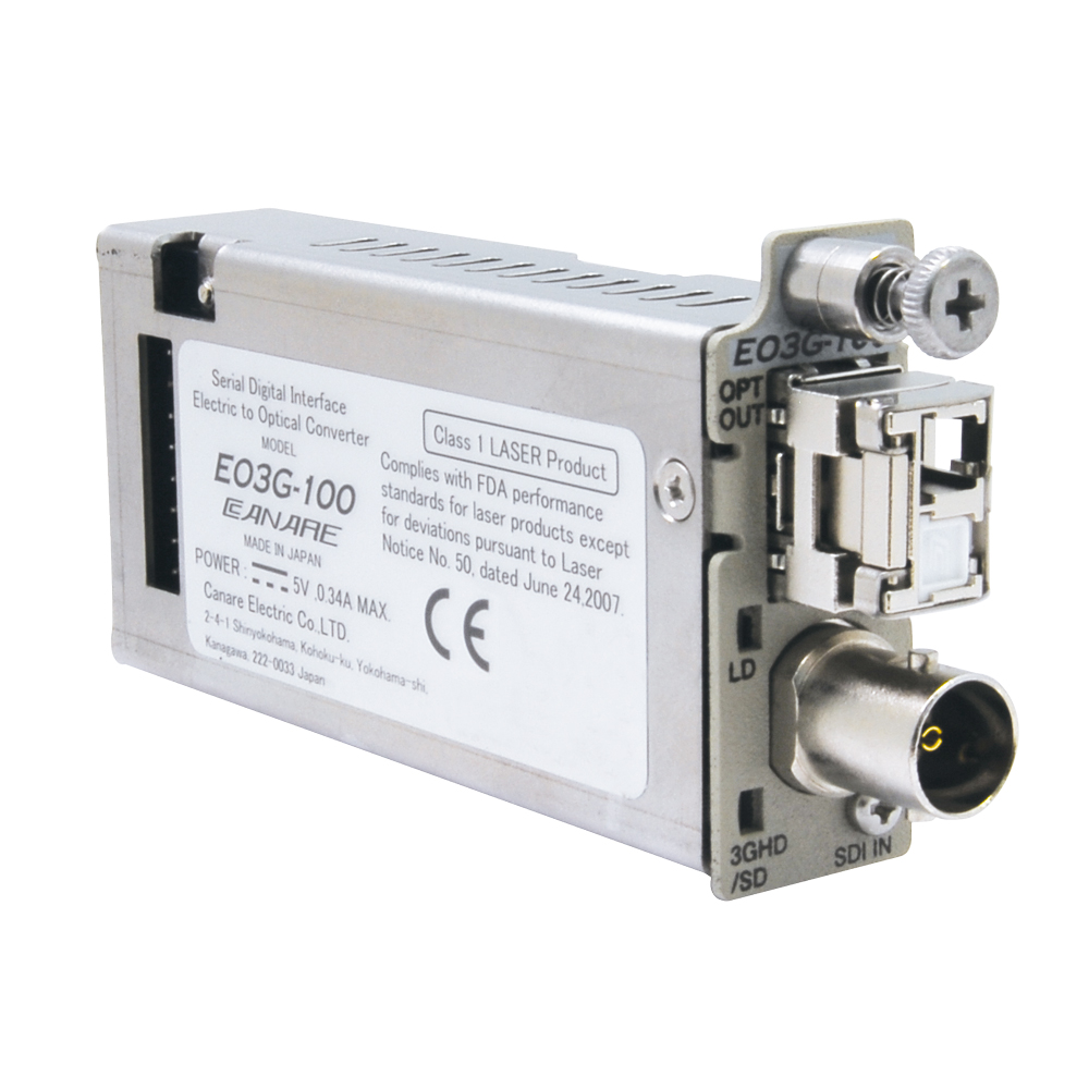
EO3G-100 -
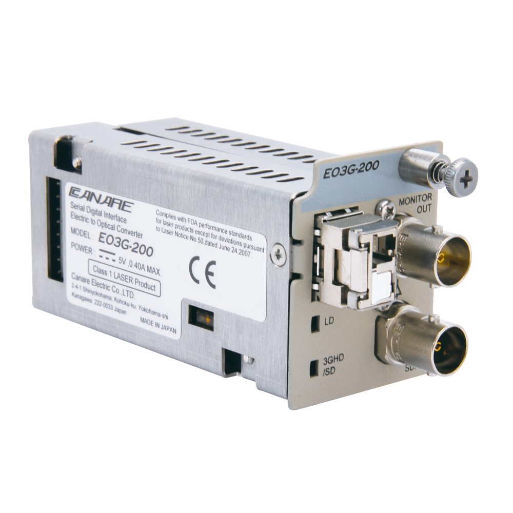
EO3G-200 -
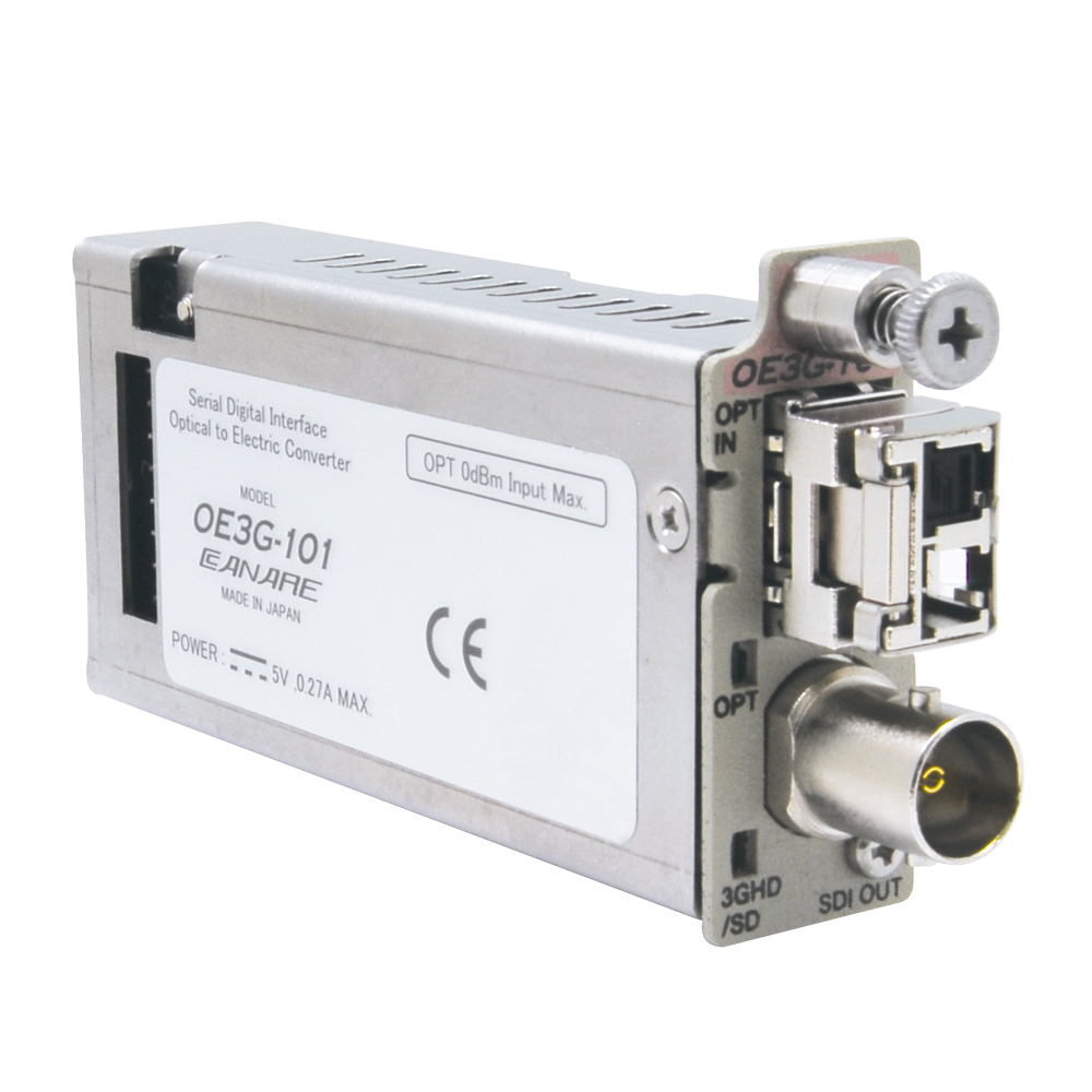
OE3G-101 -
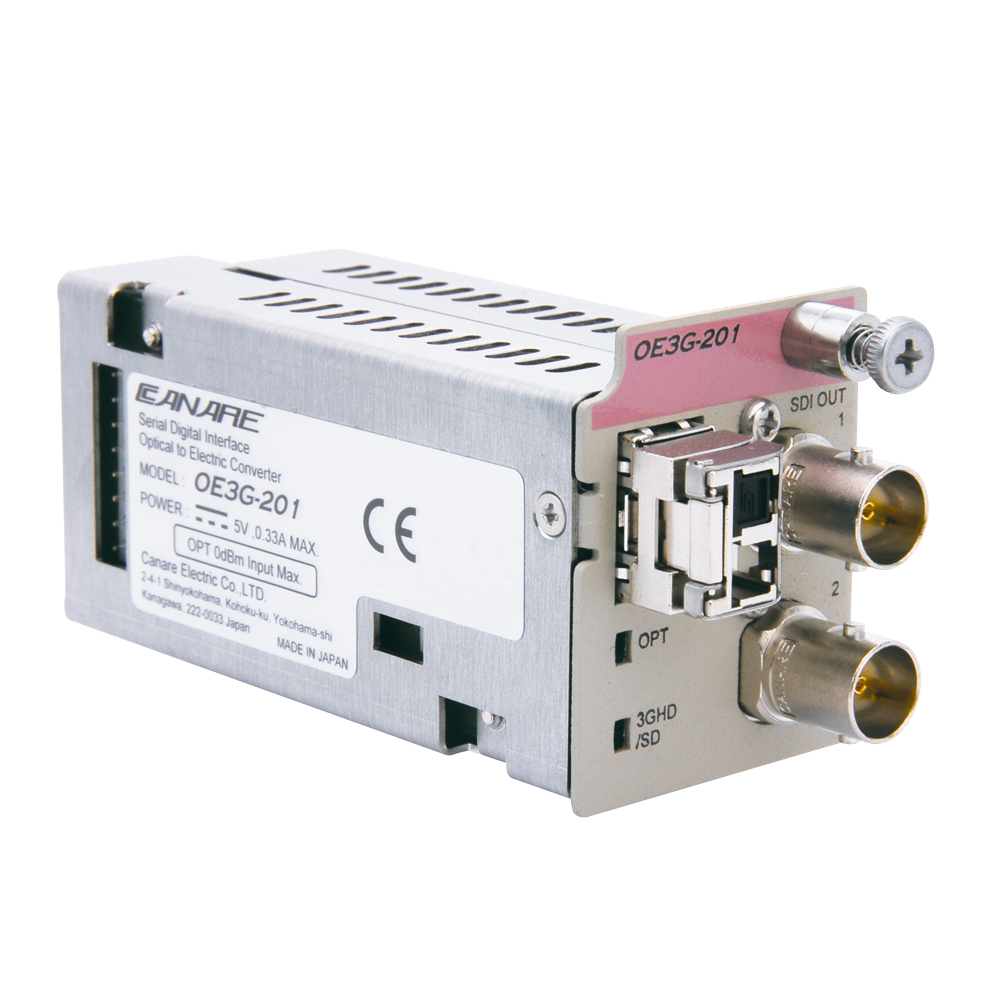
OE3G-201
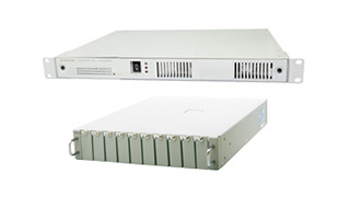
3G-SDI EO/OE Converters
An optical converter equipped with a reclocker that supports 3G-SDI signals.
- TECH DATA
- TECH NOTE
- DOWNLOAD
3G-SDI EO/OE Converters
| Model | Wavelength | Sensitivity | Dual Out | Occupancy |
|---|---|---|---|---|
| EO3G-100 | 1310 nm | -2.5 dBm | No | 1 slot |
| EO3G-200 | Yes | 2 slots | ||
| EO3G-100A-27 | 1271 nm | +2.5 dBm | No | 1 slot |
| EO3G-100A-29 | 1291 nm | |||
| EO3G-100A-31 | 1311 nm | |||
| EO3G-100A-33 | 1331 nm | |||
| EO3G-100A-35 | 1351 nm | |||
| EO3G-100A-37 | 1371 nm | |||
| EO3G-100A-43 | 1431 nm | |||
| EO3G-100A-45 | 1451 nm | |||
| EO3G-100A-47 | 1471 nm | |||
| EO3G-100A-49 | 1491 nm | |||
| EO3G-100A-51 | 1511 nm | |||
| EO3G-100A-53 | 1531 nm | |||
| EO3G-100A-55 | 1551 nm | |||
| EO3G-100A-57 | 1571 nm | |||
| EO3G-100A-59 | 1591 nm | |||
| EO3G-100A-61 | 1611 nm |
| Model | Wavelength | Emission | Monitor Out | Occupancy |
|---|---|---|---|---|
| OE3G-101 | 1200-1620 nm | -22 dBm | No | 1 slot |
| OE3G-201 | Yes | 2 slots |
Key Features and Benefits
- Supports 3G/HD/SD-SDI and DVB-ASI
- Capable of Pathological Test Pattern transmission
(SMPTE RP-178, 198 Check Field Test Pattern) - Super low latency
- Compact size
- No complicated settings
- Cost effective
- Note:
- Platform is required for power supply
Specifications
| EO3G-100 | EO3G-200 | EO3G-100A | OE3G-101 | OE3G-201 | |
|---|---|---|---|---|---|
| Convertibility | Electric to Optic | Optic to Electric | |||
| Optical Connector | 1 x LC (output) | 1 x LC (input) | |||
| Fiber Type | Single Mode | ||||
| SDI Input | 1 x 75 ohm BNC | 1 x 75 ohm BNC | 1 x 75 ohm BNC | N/A | N/A |
| SDI Output | N/A | 1 x 75 ohm BNC (no-reclocked) | N/A | 1 x 75 ohm BNC | 2 x 75 ohm BNC |
| Dimensions (mm) | 17 x 43.4 x 78.4 | 35.5 x 43.4 x 78 | 17 x 43.4 x 78.4 | 17 x 43.4 x 78.4 | 35.5 x 43.4 x 78 |
| Weight (approx.) | 100 g | 150 g | 95 g | 100 g | 150 g |
| Standards | SMPTE ST 259, 292-1, 297-1, 424, EN50083-9 | ||||
Technical Note
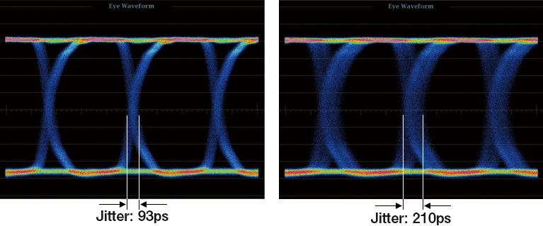
Jitter
The timing deviation of the periodic signal waveform is called jitter.
For serial data signals such as SDI signals, Jitter occurs due to the
deviation of reference clock signal, reflection caused by connection
through coaxial cables or between devices, loss of DC and high frequency
components, the influence of noise from the equipment itself or from the
outside.
In the worst case, an error occurs in clock data recovery due to this jitter
and that with SDI signals, noise may appear on the screen or signal
transmission may come to be fail.
Wavelength Multiplexing Systems
Multiplexing
“Multiplexing” is a technology that allows multiple signals with different wavelengths to be transmitted together over a single optical fiber. Three general types of multiplexing — WDM, CWDM and DWDM — offer increasing signal-carrying capacities, as described below.
Multiplexing (CWDM)
Wavelength Division Multiplexing (WDM)
WDM is the simplest form of multiplexing and uses two wavelengths of 1310nm and 1551nm. Unlike when using and optical divider, insertion loss can be kept below 0.5dB.
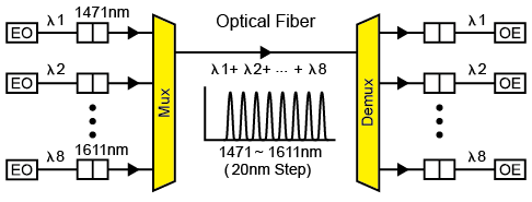
Coarse Wavelength Division Multiplexing (CWDM)
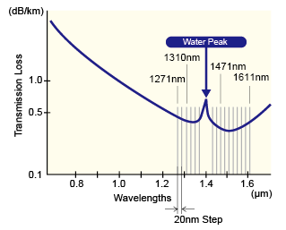
CWDM systems use 8 wavelengths (20nm grid) primarily between 1471nm and 1611nm. To these it is also possible to add 8 more between 1271nm and 1451nm to allow a maximum of 16 wavelengths to be carried as a single multiplexed transmission. An ultra-thin membrane filter on the optical multiplexer/demultiplexer (mux/demux) keeps insertion loss at just 2-3dB. *CWDM standardized through ITU G695.
Optical Converter (TX for CWDM)
Canare’s CWDM optical converter uses a DFB laser, which offers a much tighter spectrum than FP lasers. Up to 16 different wavelengths fall within 1271nm and 1611 nm in 20nm intervals. The wavelengths in the 20nm grid between 1391nm and 1411nm are not used because their proximity to the water peak results in too much attenuation
Optical Fiber Transmission Loss Characteristics
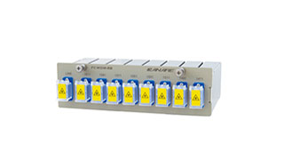
Optical Multiplexer/Demultiplexers
The optical signals output from the optical converter (TX) are combined
into a single signal by the multiplexer (mux) and transmitted along a single
optical fiber. At the receiving end, these combined optical signals are
demultiplexed (demux) to split them back into their original component 8
signals.
Optical mux/demuxers are bi-directional, so the same model can be
used for transmitting and receiving on each end. It’s also possible to use
4 wavelengths out of the 8 for transmitting and the remaining four for
receiving. Both 8-wavelength and 16-wavelength models are available,
and combining these with an optical converter allows a variety of system
constructions with many uses.
Optical Converter (RX)
Canare’s optical converter (RX) converts an optical signal comprised of 8 different wavelengths into electrical signals. This converter is common to all wavelengths and one converter is required for each wavelength.
8-wavelength CWDM system example

- Once optical fiber cables have been laid, multiplexing the transmissions carried on them eliminates the need to purchase and install new cables when more transmission lines are needed.
- Eight Canare optical converters and an FCWDM-8B mux/demuxer can be installed compactly on a single 161UPSC 1RU-size platform, effectively allowing an 8-wavelength transmission system to be achieved in just 1RU of space.