-
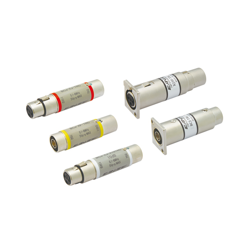
BCJ-XJ-TRC, BCJ-XP-TRC, BCJ-XJ-A10TRC, XJ3F-TRC-BCJ, BCJ-TRC-XP3M -
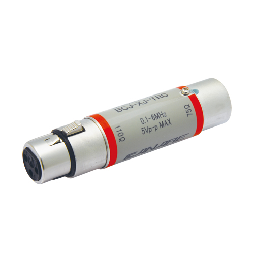
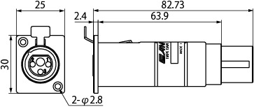
BCJ-XJ-TRC -
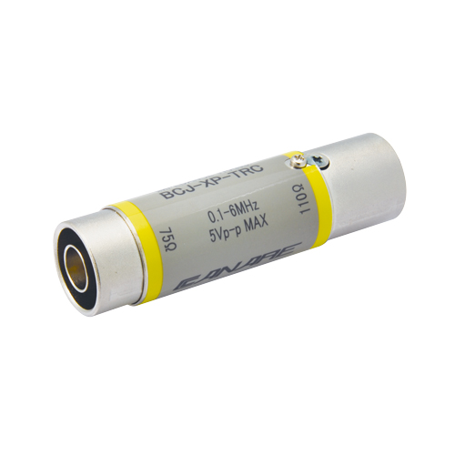
BCJ-XP-TRC -
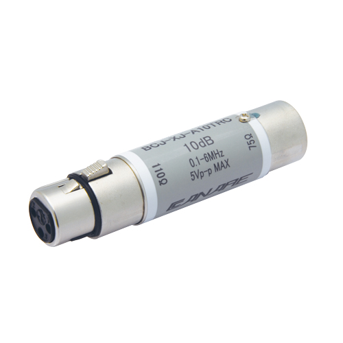
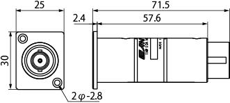
BCJ-XJ-A10TRC -
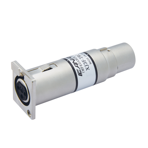
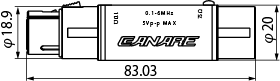
XJ3F-TRC-BCJ -
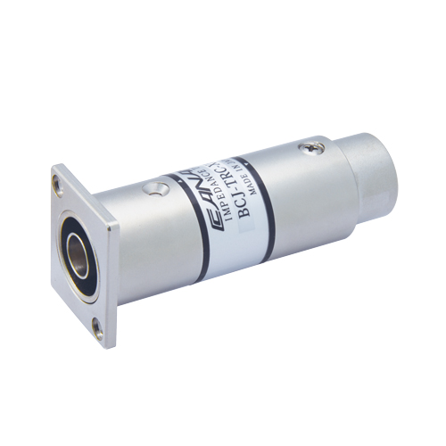
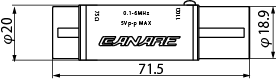
BCJ-TRC-XP3M -

BCJ-X*-TRC Wiring Diagram -

BCJ-XJ-TRC Wiring Diagram
110 ohm - 75 ohm Impedance Transformers
Passively convert AES/EBU digital audio signals from 110 ohm/XLR3 output to a 75 ohm BNC coaxial cable and then back again to a 110 ohm/XLR3 input.
- TECH DATA
- TECH NOTE
- DOWNLOAD
110 ohm - 75 ohm Impedance Transformers
| Model | Description | Standard package |
|---|---|---|
| BCJ-XJ-TRC | XLR3 (F) - BNC Jack | 1 pc |
| BCJ-XP-TRC | XLR3 (M) - BNC Jack | 1 pc |
| BCJ-XJ-A10TRC | XLR3 (F) - BNC Jack, 10dB Attenuation Pad | 1 pc |
| Model | Description (Front - Back) | Flange Type | Standard package |
|---|---|---|---|
| XJ3F-TRC-BCJ | XLR3 (F) - BNC Jack | ITT XLR-F77 | 1 pc |
| XJ3M-TRC-BCJ | XLR3 (M) - BNC Jack | 1 pc | |
| BCJ-TRC-XP3F | BNC Jack - XLR (F) | 1 pc | |
| BCJ-TRC-XP3M | BNC Jack - XLR (M) | 1 pc | |
| XJ3F-A10TRC-BCJ | XLR3 (F) - BNC Jack, 10dB Attenuation Pad | 1 pc | |
| BCJ-A10TRC-XP3F | BNC Jack - XLR3 (F), 10dB Attenuation Pad | 1 pc |
Key Features and Benefits
- SMPTE 276M and AES3 transmission standards
- Coaxial transmission of 2 channel digital audio
- Allows longer cable runs than 110 ohm twisted pair
- AES/EBU signal distribution using Canare 75 ohm video patchbays
BCJ-XJ-TRC
BCJ-XP-TRC
XJ3F-TRC-BCJ
BCJ-TRC-XP3M
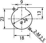
Panel Hole Dimensions
| BCJ-XJ-TRC, BCJ-XP-TRC | BCJ-XJ-A10TRC | ||
|---|---|---|---|
| AES/EBU Transmitter ( V ) |
Transformer Out
( V ) |
AES/EBU
Transmitter ( V ) |
Transformer Out
-10dB Pad ( V ) |
| 2.0 | 1.60 | 2.0 | 0.50 |
| 3.0 | 2.39 | 3.0 | 0.75 |
| 4.0 | 3.18 | 4.0 | 1.01 |
| 4.5 | 3.60 | 4.5 | 1.13 |
| 5.0 | 3.98 | 5.0 | 1.26 |
| 6.0 | 4.78 | 6.0 | 1.51 |
| 7.0 | 5.58 | 7.0 | 1.76 |
| 8.0 | 6.38 | 8.0 | 2.02 |
| 9.0 | 7.18 | 9.0 | 2.27 |
| 10.0 | 7.98 | 10.0 | 2.52 |
Technical Note
Voltage Standing - wave Ratio (VSWR) and Return Loss
Terminating the receiving end of a limited length coaxial cable using a resistance value not equal to its characteristic impedance creates a reflected wave that returns back down the cable to the sending end. The result is interference developing between the travelling wave and the return wave which results in a standing wave that causes voltage levels to fluctuate. The degree to which terminating resistance matches the characteristic impedance is indicated using the VSWR or voltage standing-wave ratio standard shown in Fig. 1. Going hand in hand with the VSWR ratio is the return loss factor which measures the size of the reflected wave current in relation to the travelling wave current. (See Fig. 2)
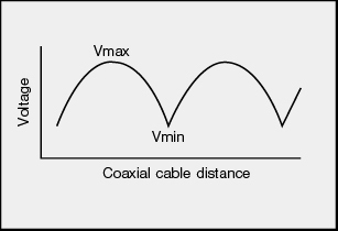
Fig. 1 Voltage Distribution Over Coaxial Cable
| VSWR | Return Loss (dB) |
|---|---|
| 2 | 9.54 |
| 1.5 | 13.98 |
| 1.2 | 20.83 |
| 1.1 | 26.44 |
| 1.05 | 32.26 |
| 1.02 | 40.09 |
| 1.01 | 46.06 |
Fig. 2 VSWR to Return Loss Conversion Table