-
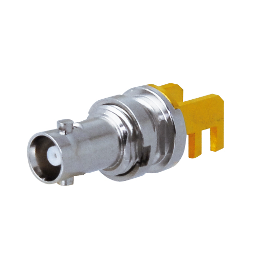
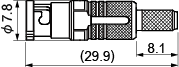
HBCP-D25HDA -
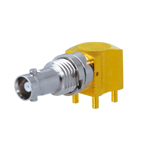
HBCJ-LRK -
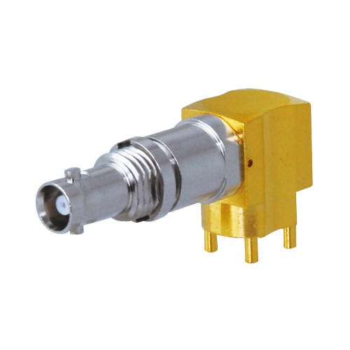
HBCJ-LRK1 -
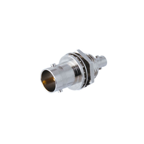
HBCJ-FEMK -
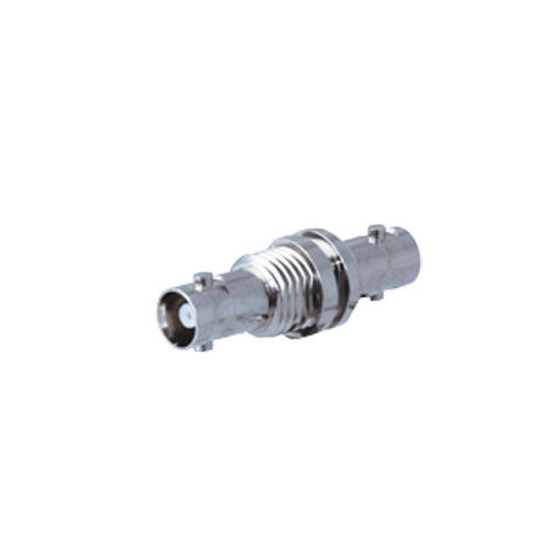
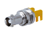
HBCJ-JRK -
BCJ-HBCJK
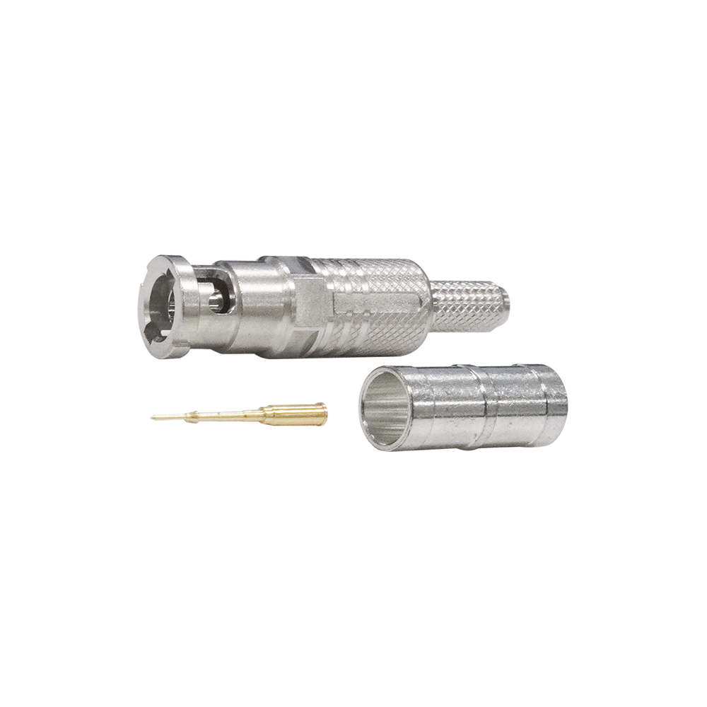
75 ohm Micro BNC Connectors
Micro BNC connectors supporting 12G-SDI. The micro BNC is about half the size of standard BNC and is ideal for high-density mounting.
All Canare micro BNC connectors are designed for SMPTE ST 2082-1 spec. Ideal for cabling 12G-SDI routers, switchers, and SFP modules. PCB connectors will allow greater flexibilities of the number of video interface.
Key Features and Benefits
- Lock mechanism used on insulation improves reliability by preventing shifting or detaching of the center pin.
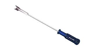
- TECH DATA
- TECH NOTE
- DOWNLOAD
75 ohm Micro BNC Connectors
| Model | Suitable Cable | Center Pin | Sleeve | Die Set | Extraction Tools |
Standard package |
|
|---|---|---|---|---|---|---|---|
| Canare | Others | ||||||
| HBCP-D25HDA | L-2.5CHD, L-2.5CHLT | 1855A | BN1214 | BN7136 | TCD-D253F | BET-D/H, BET-HBNC, Common Tool |
20 pcs |
| HBCP-D25HWA | L-2.5CHWS, V4-2.5CHW | - | BN1214 | BN7141 | TCD-D253F | ||
| HBCP-D33UHDA | L-3.3CUHD | - | BN1215 | BN7003A | TCD-D253F | ||
| HBCP-D53A | L-4.5CHD, V4-4.5CHD | 1694A | BN1218 | BN7016 | TCD-D534F | BET-D/H, Common Tool |
|
| HBCP-D55UHD | L-5.5CUHD | - | BN1219 | BN75004A | TCD-D55UHD | ||
Key Features and Benefits
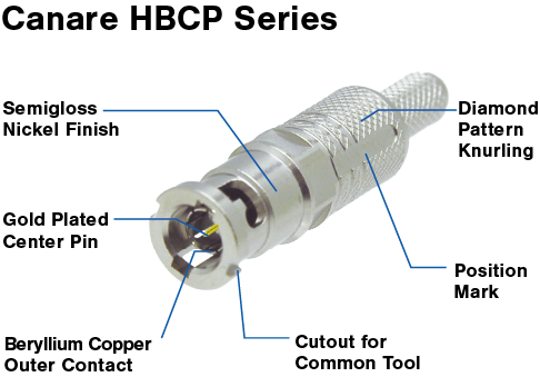
- Return loss : 26dB @ 3GHz, 20dB @ 6GHz, 15dB @ 12GHz.
- SMPTE ST 2082-1 compliant.
- Canare crimp design ensures quick and reliable installation.
- Gold plated "snap locks" center pin.
- Beryllium copper outer contact.
- Come with a position mark on the body for better visibility mating.
- Note:
- Be sure to use Canare Crimp Tool.
-
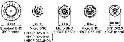
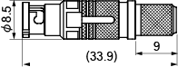
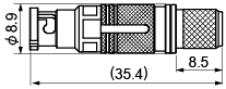
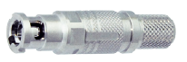
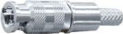
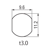
Comparison of connector body diameter.
* For reference only -
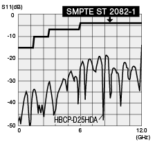
Return loss for HBCP-D25HDA
-
HBCP-D25HDA
-
HBCP-D53A
-
HBCP-D55UHD
| HBCP-D25HDA, HBCP-D25HWA, HBCP-D33UHDA |
HBCP-D53A, HBCP-D55UHD |
HBCP-D25HD, HBCP-D25HW, HBCP-D33UHD, HBCP-D53 |
||
|---|---|---|---|---|
| Appearance | 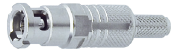 |
 |
 |
|
| Return Loss | ≥15dB@DC-12GHz | ≥15dB@DC-12GHz | ≥8dB@DC-12GHz | |
| Connector O.D. | φ7.8mm | φ8.5-8.9mm | φ7.82-8.5mm | |
| Extraction Tools / Distance Between Center of Plugs |
BET-D/H / 12mm | YES | YES | YES |
| BET-HBCP / 8mm | YES | NO | NO | |
| Common Tools / Min. 8mm | YES | YES | NO | |
| Application | Rack wiring, Extremely narrow space, Video SFP |
50-100M distance range, 12G-SDI sensitive connection |
Rack wiring, Narrow space, 12G-SDI routers/switchers |
|

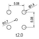
Distance Between
Center of Plugs : 8mm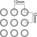
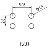
Distance Between
Center of Plugs : 12mm
| Type | Model | Description | Nut Driver Bit | Standard package |
|---|---|---|---|---|
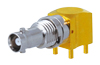 |
HBCJ-LRK | Right Angle | NDT-HBC | 20 pcs |
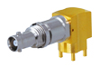 |
HBCJ-LRK/1 | Right Angle, Long type | ||
 |
HBCJ-FEMK | Edge Mount |
Key Features and Benefits
- SMPTE ST 2082-1 compliant
- Combination of HBCJ-LRK/1 and HBCJ-FEMK is effective for staggered arrangement
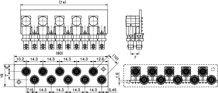
- Note:
- Nut driver bit NDT-HBC is required to mount the nut on the panel.

| Type | Model | Description | Nut Driver Bit | Standard package |
|---|---|---|---|---|
 |
HBCJ-JRK | Jack to Jack | NDT-HBC (for panel mounting) | 20 pcs |
 |
BCJ-HBCJK | BNC Jack to Micro BNC Jack | N/A |
Key Features and Benefits
- SMPTE ST 2082-1 compliant
- Panel mountable
- Note:
- Nut driver bit
NDT-HBC is required to mount the nut on the panel.
(except for BCJ-HBCJK)
| HBCJ | BCJ-HBCJK* |
|---|---|
 |
 |
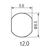
* BCJ-HBCJK accept insulation bushing IU-7/16. See the panel hole with IU-7/16.
| HBCJ-LRK, HBCJ-LRK/1 | BCJ-FEMK |
|---|---|
 |
 |
Technical Note
Voltage Standing - wave Ratio (VSWR) and Return Loss
Terminating the receiving end of a limited length coaxial cable using a resistance value not equal to its characteristic impedance creates a reflected wave that returns back down the cable to the sending end. The result is interference developing between the travelling wave and the return wave which results in a standing wave that causes voltage levels to fluctuate. The degree to which terminating resistance matches the characteristic impedance is indicated using the VSWR or voltage standing-wave ratio standard shown in Fig. 1. Going hand in hand with the VSWR ratio is the return loss factor which measures the size of the reflected wave current in relation to the travelling wave current. (See Fig. 2)
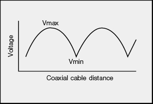
Fig. 1 Voltage Distribution Over Coaxial Cable
| VSWR | Return Loss (dB) |
|---|---|
| 2 | 9.54 |
| 1.5 | 13.98 |
| 1.2 | 20.83 |
| 1.1 | 26.44 |
| 1.05 | 32.26 |
| 1.02 | 40.09 |
| 1.01 | 46.06 |
Fig. 2 VSWR to Return Loss Conversion Table