-
75 ohm KC IMAGE -
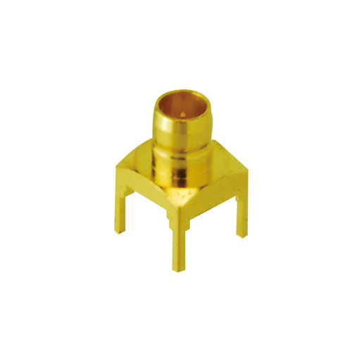
KCM-PC -
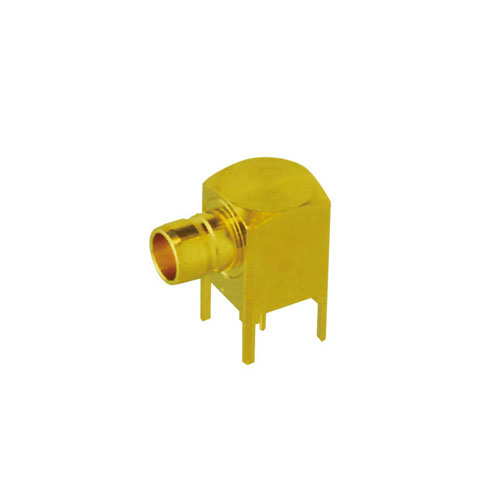
KCM-LR -
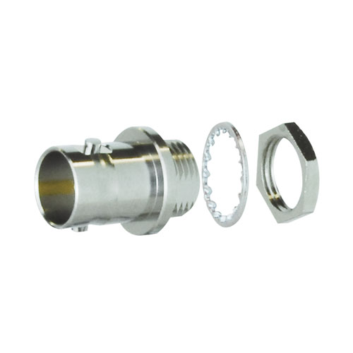
BCJ-KCM -
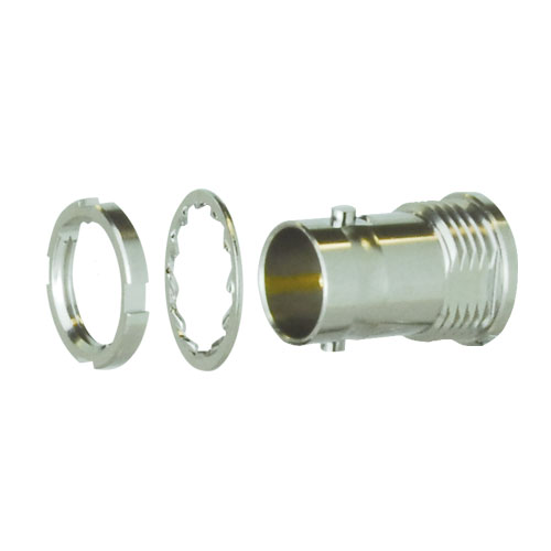
BCJ-FKCM -
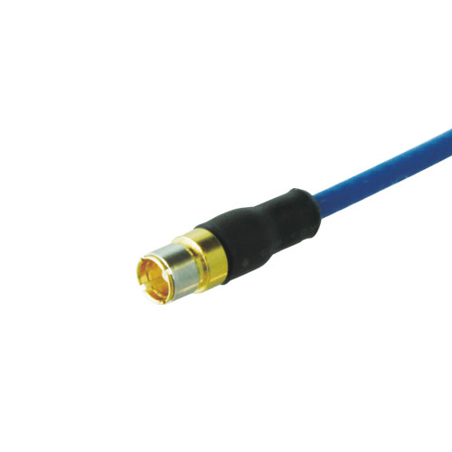
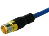
KC1.2R-****-S -
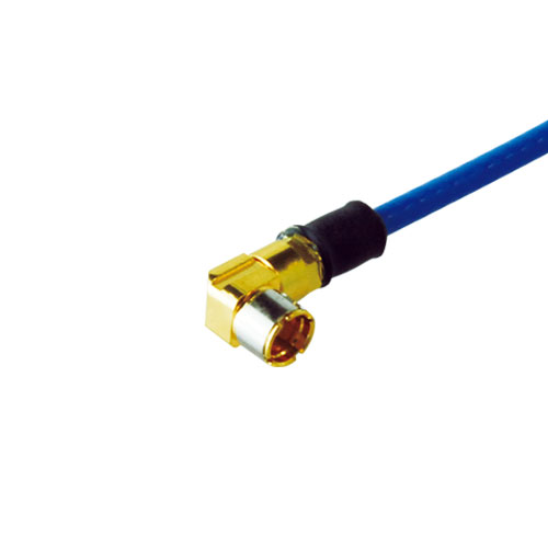
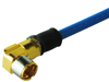
KC1.2R-****-L -

Ordering Information
75 ohm Micro-miniature Coaxial Connectors
Canare's exclusive micro miniature connectors, KC series: specially designed for 4K/8K UHD equipment. Our PCB mount solutions provide flexible layout and reliable connectivity on 12G-SDI signal path. Products are 12GHz verified and guaranteed SMPTE ST2082-1.
- TECH DATA
- TECH NOTE
75 ohm Micro-miniature Coaxial Connectors
| Type | Model | Description | Standard package |
|---|---|---|---|
 |
KCM-PC | Straight | 20 pcs |
 |
KCM-LR | Right Angle | 20 pcs |
| Type | Model | Description | Nut Driver Bit | Standard package |
|---|---|---|---|---|
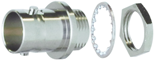 |
BCJ-KCM | Rear Mount, Hex Nut | - | 20 pcs |
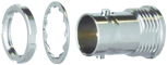 |
BCJ-FKCM | Front Mount, Grooved Nut | NDT-7/16 | 20 pcs |
| Type | Model | Description | Length(mm) | ||
|---|---|---|---|---|---|
| Plug A | Plug B | Jacket | |||
 |
KC1.2R-0015-S | Straight | Straight | FEP(blue) | 150 |
| KC1.2R-0020-S | 200 | ||||
| KC1.2R-0030-S | 300 | ||||
 |
KC1.2R-0015-L | Right Angle | Right Angle | 150 | |
| KC1.2R-0020-L | 200 | ||||
| KC1.2R-0030-L | 300 | ||||
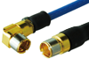 |
KC1.2R-0015-SL | Straight | Right Angle | 150 | |
| KC1.2R-0020-SL | 200 | ||||
| KC1.2R-0030-SL | 300 | ||||
Key Features and Benefits
- DC to 12 GHz; meets the SMPTE 2082-1 return loss requirements.
Return loss: 26 dB @ 1.5 GHz, 20 dB @ 3 GHz, 15 dB @ 6 GHz, 10 dB @ 12 GHz - Snap-on engaging
- Durable design; beneficial for maintenance.
- Temperature range; -25 to 85 degree C
- The best flexibility on PCB design
- Note:
- BCJ-FKCM requires the nut driver bit NDT-7/16 for installation and removal.
Contact for the details.

KCM-PC

KCM-LR

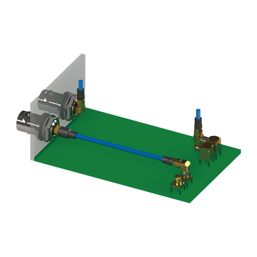
KC1.2R-****-SL

Interface to Termination
(reference)
Technical Note
Voltage Standing - wave Ratio (VSWR) and Return Loss
Terminating the receiving end of a limited length coaxial cable using a resistance value not equal to its characteristic impedance creates a reflected wave that returns back down the cable to the sending end. The result is interference developing between the travelling wave and the return wave which results in a standing wave that causes voltage levels to fluctuate. The degree to which terminating resistance matches the characteristic impedance is indicated using the VSWR or voltage standing-wave ratio standard shown in Fig. 1. Going hand in hand with the VSWR ratio is the return loss factor which measures the size of the reflected wave current in relation to the travelling wave current. (See Fig. 2)
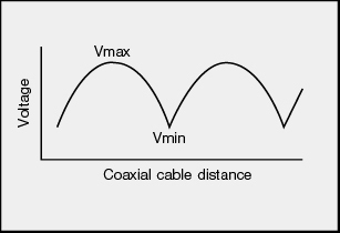
Fig. 1 Voltage Distribution Over Coaxial Cable
| VSWR | Return Loss (dB) |
|---|---|
| 2 | 9.54 |
| 1.5 | 13.98 |
| 1.2 | 20.83 |
| 1.1 | 26.44 |
| 1.05 | 32.26 |
| 1.02 | 40.09 |
| 1.01 | 46.06 |
Fig. 2 VSWR to Return Loss Conversion Table